Reverse engineering · 3D modelling · Manufacturing drawings
Piece-by-piece reconstruction of an ERLO pillar drill
A fall cracked the machine's main body and left it unusable. I reconstructed the complete drill in 3D, one part at a time, and prepared the drawings required to manufacture its components again.
Starting point
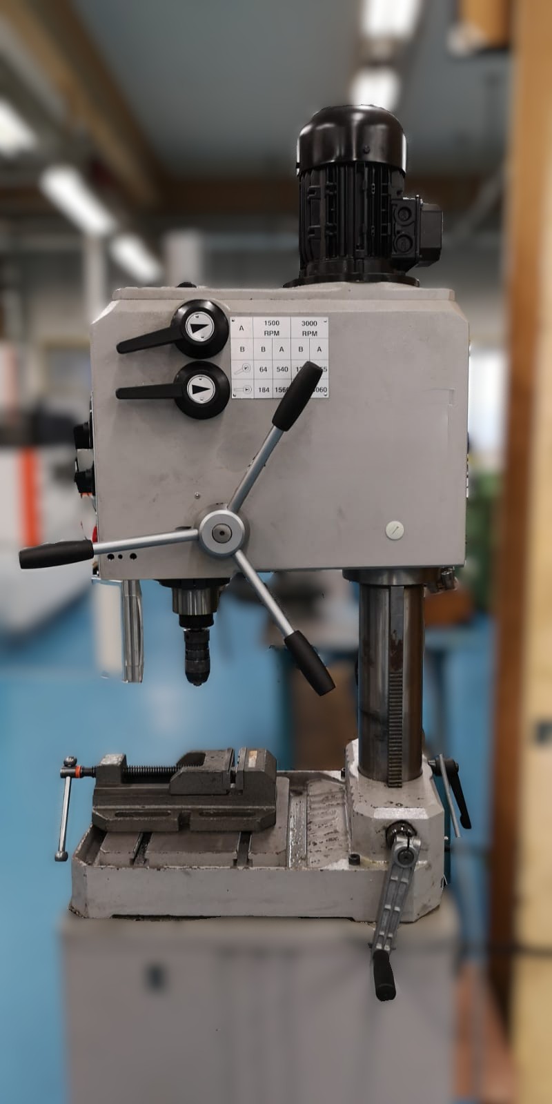
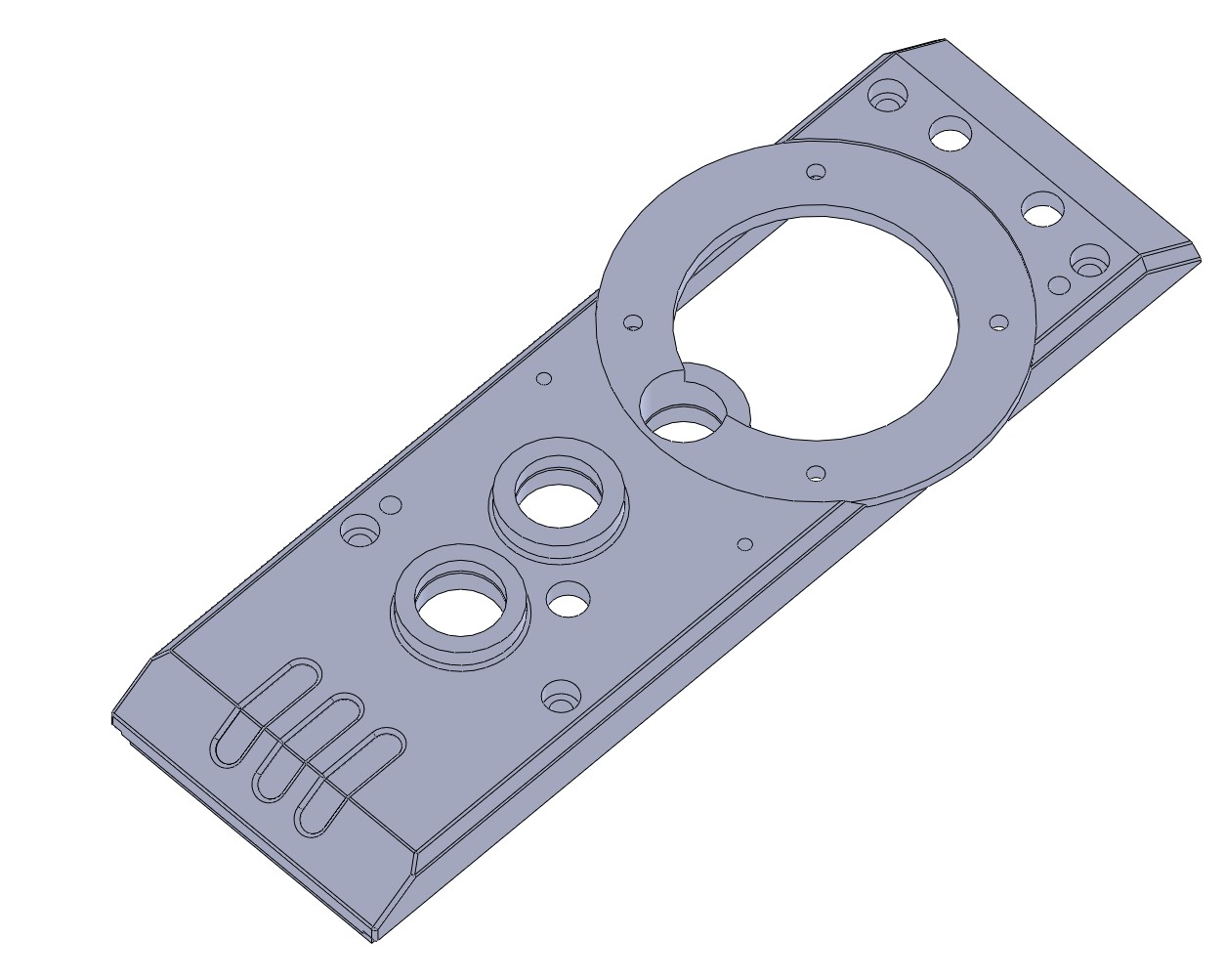
The pillar drill had fallen in the workshop. The impact opened a crack in the main body, the component that houses and locates much of the head mechanism, and the machine could no longer be used.
The aim was not merely to reproduce its external appearance. The assembly had to be reconstructed in enough detail to define each component, verify how it fitted with the others and produce useful manufacturing and assembly documentation.
From assembly to exploded view
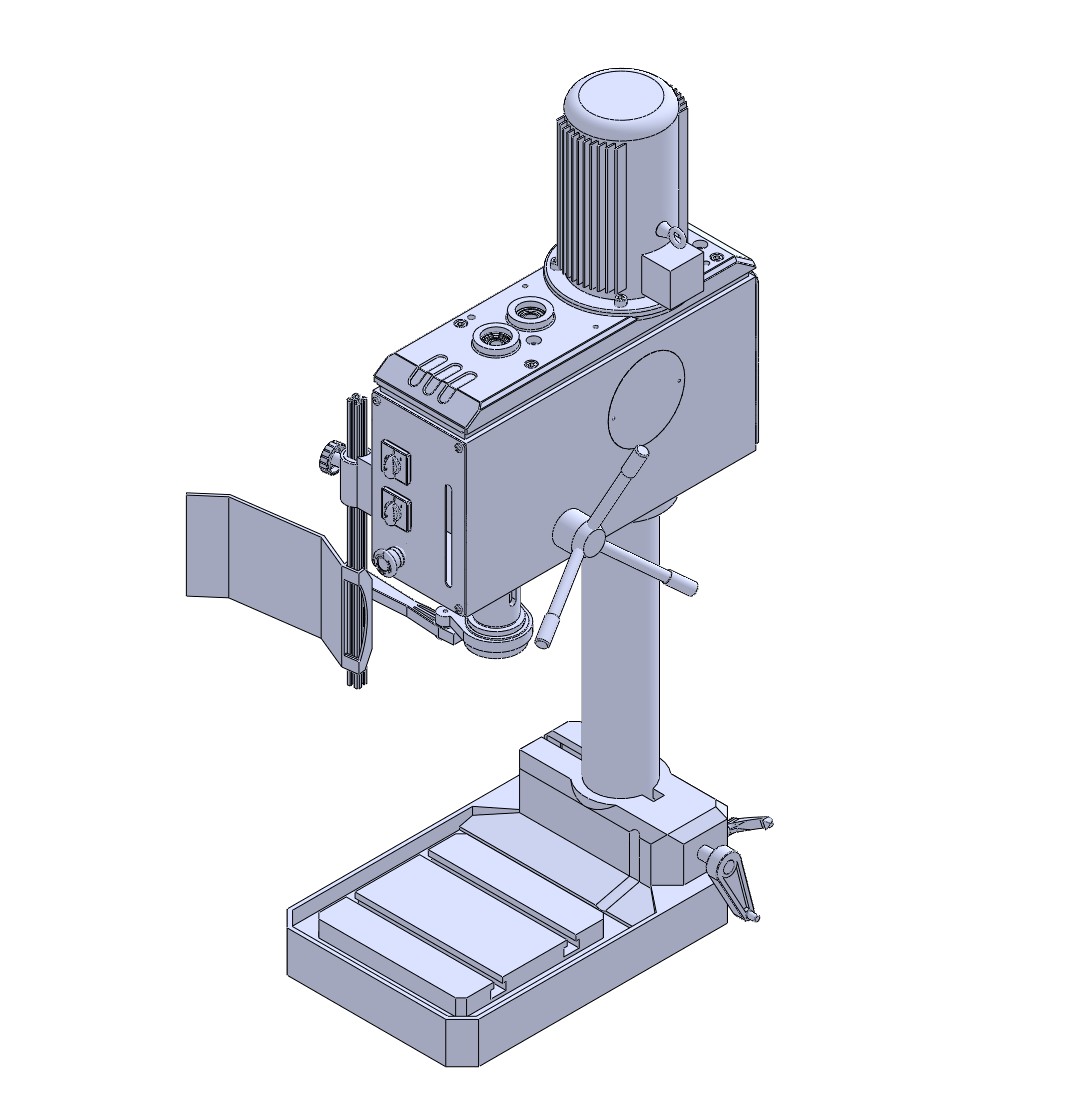
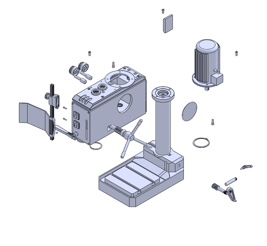
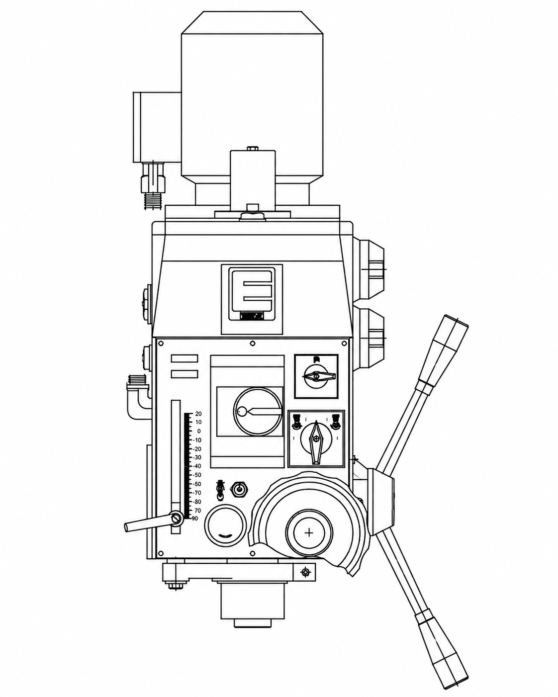
I organised the reconstruction around the machine's architecture: base and column, head body, spindle, transmission, manual feed, motor, covers and auxiliary elements. The ERLO manual helped identify functions and relationships between mechanisms; the geometry was resolved from the physical machine.
Each part was modelled within the assembly to preserve references, axes, supports and mounting positions. This approach allowed interference checks and maintained traceability between each component and the complete machine.
Head reconstruction
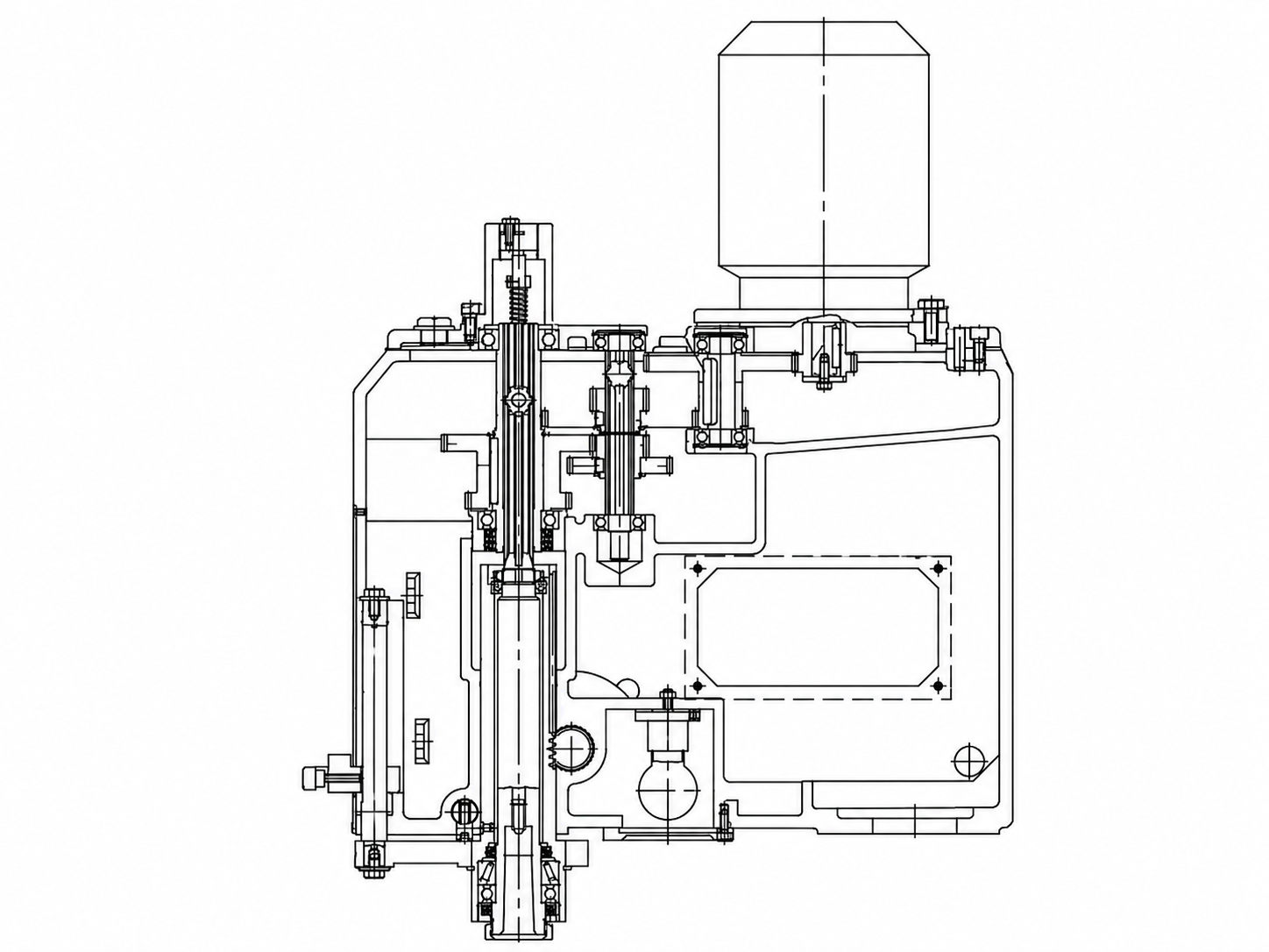
The head contained most of the complexity. The reconstruction had to preserve the relative positions of the spindle, shafts, bearings, gears, feed system and motor connection, as well as the housings and access points in the main body.
Section views made it possible to review the path of the mechanisms inside the casing and verify that the exterior model followed a coherent internal arrangement rather than a visual approximation.
Manufacturing drawings
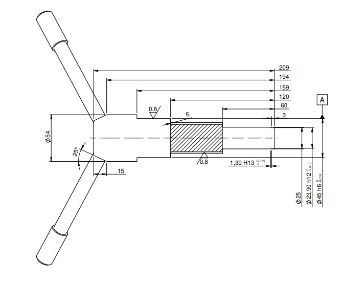
The 3D model became the basis for documenting the parts that had to be manufactured again. The drawings translate the geometry into verifiable dimensions and include the fits, finishes and sections required to interpret each component in the workshop.
The documentation remains linked to the assembly: a change to an individual part can be reviewed in context before its drawing is updated. The result is not simply a visual model, but an assembly prepared for manufacturing and reassembly.
Outcome
The machine was defined as a complete 3D assembly with a set of manufacturing drawings. The result preserves the mechanical logic of the ERLO drill and documents the parts required to undertake its reconstruction without relying solely on the cracked original body.